Ravel Conventional Smoke Detector Connection Diagram

Toll free no.
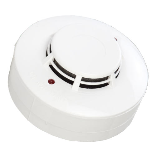
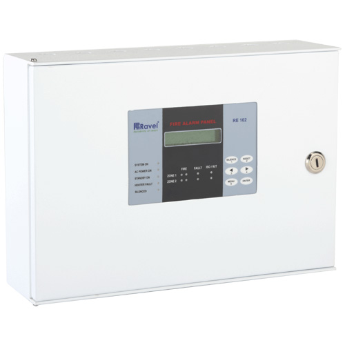
Ravel conventional smoke detector connection diagram. The microprocessor based ul listed 4 zone conventional fire alarm control panel the system has 16 x 2 lcdcharacter 4 zones detection circuit 3 common potential free contacts 2 common nac sounder output inbuilt rs 485 for repeater connectivity wall ceiling mounted switch mode power supply smps battery polarity deep discharge protection. Convention fire alarm systems are most common fire alarm system suitable for everywhere. Here i show you how to connect a smoke detector in a loop line. These detectors are low profile and have dual led s for 360o visual indication.
It has an unique protocol chamber designed to sense smoke. Here i show the layout diagram of fire alarm detection system. Ravel electronics pvt ltd is your trusted partner bringing to you something of the best quality and advanced fire alarm panels that are easy to install to detect smoke through light sensors or when smoke particles pass thru the chamber of the optical detector. The groups lifeline has its origins in 1986.
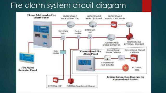
This is the basic fire alarm system used in household wiring. Two type of fire alarm detection system 1 addressable system 2 conventional system modernexpe. The led s are blinking in normal operating condition whereas the steady state indicates fire status. The re 316s 2l conventional detectors are designed to work with all conventional panel.
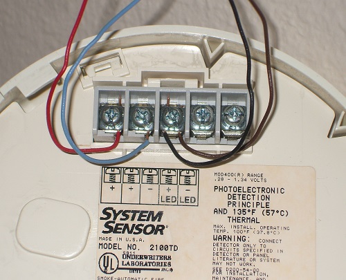
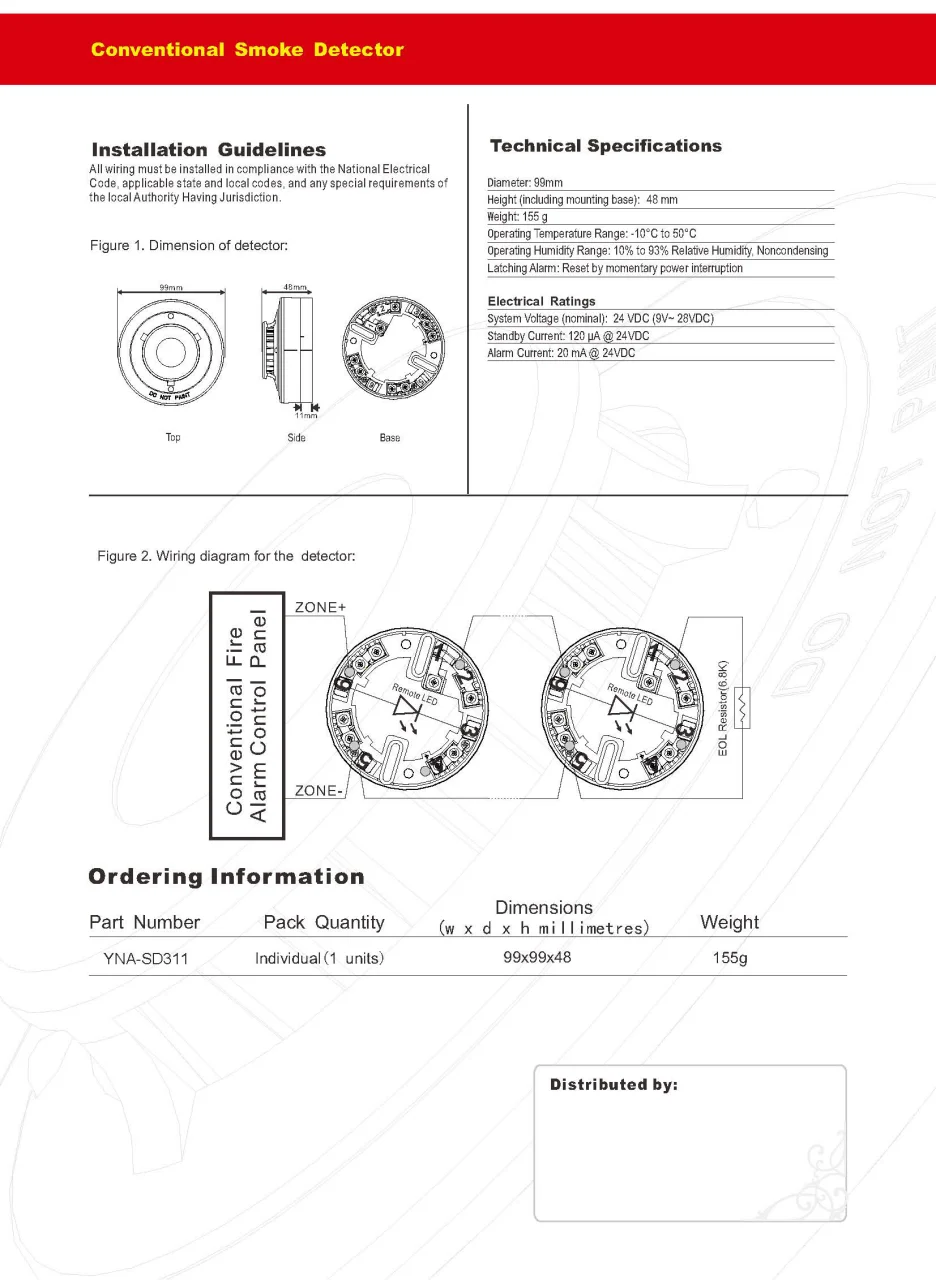
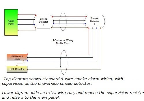
How to wire to a conventional or addressable fire panel. Warning to prevent detector. Figure 1 a shows the typical wiring diagram of the 2 wire multiple station smoke heat detector system. Ravelfire have designed these fire alarm system by using best technology they are reliable and sensitive.
In our basic wiring diagram a single or multiple heat and smoke detectors are installed in the home by connecting the live line or hot neutral ground and an interconnected wire to the alarm. There are two types of fire panels conventional types which have zones which are connected directly to devices such as optical beam smoke detectors or flame detectors and analogue addressable types which have a loop bus onto which addressable devices can be connected. In this way it scatters light and triggers the alarm. Figure 1 b shows the typical wiring diagram of the 4 wire multiple station smoke heat detector system.
Do not place links between the wiring positions of terminals 2 and 5 to provide power supervision.

